In this example, we will refer to a fictitious night of data which, in order of acquisition, looks like this. If you have very short exposure times or very narrow filters (so the sky level is near zero), you may want to follow a more tedious but exact processing procedure. This version does everything in FITS file format (no more *.imh images).
I. If you didn't do this before: from the CCD PC, ftp all frames to your account on baade.
II. Convert from integer (raw) to floating-point (processed) data formats and put Darktime, ST, Airmass, HJD into headers.
III. Prepare the Zero frame.
IV. Create a Dark frame for the correct CCD temperature.
V. Prepare the Flat Field frames for each filter used (Note: uses dome flats, sky flats & illumcor).
VI. Process all star observations (do Trim, Zero, Dark, Flat and Illumination corrections).
VII. Notify team members where images can be found. Andy will backup all processed and raw images to DVD, and inform you when images can be deleted.
At any point, if you have trouble, you may get a jump-start from the troubleshooting page.
Updated 2010 Oct 11 -- ACL
Overview: Copy the images you took from the CCD PC in the warmroom to baade. It is handy to do this immediately after you observe, while the CCD is warming (it only takes a few minutes).
In this example, we will process the data in a directory on baade called /data/layden/PHOT/02MAY30. You should store the unprocessed *.fit images in a subdirectory called RAW (in this example, /data/layden/PHOT/02MAY30/RAW), so if something goes wrong with processing the images you can easily recover the originals. It is also easy for use to archive (copy to tape or DVD) the raw images.
1) First, enter MaxIM_DL (shortcut on desktop) and look through the list of images you took. Do any have incorrect titles (according to our naming convention)? If so, correct them now.
2) From the CCD PC, get into PSFTP ("PuTTY's secure file transfer protocol"):
Updated 2011 May 26 -- ACL
Overview: The image header contains many "keywords" and their values that are required for image processing and analysis (type "imhead yourfile.fits l+" to look at the keywords and values for a file called yourfile.fits). In particular, CCDPROC needs the keyword "DARKTIME" to do the dark current corrections, but MaxIM_DL does not write DARKTIME into the header.
Also, we will express the time of our variable star observations in "Heliocentric Julian Date" (HJD), the number of days since some semi-arbitrary date about 2.5 million days ago. IRAF needs to know the Universal Time (UT), UT-date (DATE-OBS), exposure time (EXPTIME), and Sidereal Time (ST) of the observation in order to compute HJD. We need to estimate the ST when each image was taken from the UT (written into the header) and from the UT/ST "zeropoint" you logged at the beginning of the night.
Note: This and the remaining steps in this manual will be done while logged into baade (remotely).
1) First, there are a bunch of files and programs that you will need for processing. Here, we will copy them all to the current directory on baade. [Hint: Cut/paste this command with the mouse to ensure accuracy.]
cl> cp /data/layden/BGTEL/PROCESSF/* .
2) The following IRAF script will convert all of the raw images (RAW/*.fit) from their original, integer (IRAF calls it "ushort") data format to floating-point, decimal (IRAF calls it "real") data format. The former treats all intensity values as integers (e.g., 501, or 12345) and is handy because it takes up less space on disk. The latter expands the precision level to include fractional intensities (like 500.93 and 12345.67) -- it takes up more space on disk and calculations take a little longer, but it preserves more precision as we start manipulating the images mathematically. [To see the things it has done, type "!page readwrite.cl"]. The question about the maximum trustworthy counts sets very non-linear pixel intensities to an "out of bounds" value that DAOPHOT will recognize as saturated (set to 11500 on 2010 Feb 16).
cl> cl < fit2fits.cl
	Enter maximum trustworthy counts (12000): 11500
cl> imhead *.fits
(look at all those files!!)
Keep the FITS-format images in /RAW! They are a convenient backup in case you make an error in later processing steps. Plus, we will make a tape copy of the raw and processed images for our archive. Andy will inform you when it is OK to delete the images in /RAW .
3) We will correct all the keywords using a task written by Nick Pearson (1999). This script will ask you several questions, and you should respond as follows (in red).
cl> cl < headadd.clName of file containing stars RA and Dec: stars.allist Epoch of coordinates: 2000 UT at beginning of night: 12 03 14.3 (for example) ST at beginning of night: 07 14 00.0 (for example)
The UT and LST entries are the times you wrote on the top of the logsheet -- they enable the program to compute the ST at any time during the night. Errors made here secretly propagate throughout the analysis procedure and ruin our final light curves, so take care! If you don't have the UT/ST zero-point from the logsheet, look here.
This corrects all the header information. A log of all the operations performed is written to the file "headadd.log", and the file "headadd_go.cl" is the script that was run.
Just to be sure all went well, compare the old values (from MaxIM_DL) with the new values (that IRAF wants). They should be the same (no darktime for biases):
cl> hselect *.fits $I,exptime,darktime yes
Also, look to see that all the star images got reasonable values of UTdate/time, ST, airmass, and HJD (compare with the log sheets you wrote while observing).
cl> hselect *_*.fits $I,date-obs,time-obs,st,airmass,hjd yes
Note: If there are any errors, contact Andy. The program is pretty tricky, and it is not 100% "bulletproof".
Updated 2010 Feb 16 -- ACL
Overview: The 8 or so bias frames taken at the beginning and/or end of the night will be trimmed (the rows Y>1019 and the columns X>1022 are bad), and then combined into a master frame, "Zero.fits", which contains a 2-D map of the intensity-structure in the bias. The median value of Zero.fits should be about 505 (+/- 5 or so) counts.
1) Make a list of the bias frames taken at the beginning and/or end of the night (when the dome was shut and the lights were off). These are probably the only biases you have. Check to be sure using IMHEAD. If there are other biases in your list, delete the filenames using emacs [Hint: these emacs keystrokes may be helpful in your editing here and elsewhere].
cl> files *bias*.fits >> bias.list
cl> imhead @bias.list
cl> emacs bias.list (if needed)
2) Open the following packages in IRAF. The file "dpar.ccdred" is a file (page it if you like) that contains the parameter settings for the IRAF task called CCDRED. The "cl < ..." command enters those parameters into the task -- easier than doing it manually with 'epar'. The link shows the correct parameters for CCDRED.
cl> noao
no> imred
im> ccdred
cc> cl < dpar.ccdred2
cc> lpar ccdred
3) Use CCDPROC to trim the bad columns off the bias images, and convert them to real format. Use the "cl < ..." command to inject the parameters directly into CCDPROC. Use LPAR to see what the settings are, and run it with the CCDPROC command..
cc> cl < dpar.ccdproc_bias
cc> lpar ccdproc
cc> ccdproc @bias.list
4) Check out the results using CCDLIST. The images are now smaller in size, [1022,1019] rather than [1024,1024]. They are also real (decimal) format rather than short (integer), so they take up more space on the disk. The [T] means that only the Trim processing step was performed on these images.
cc> ccdlist @bias.list
5) Combine these trimmed biases into a high signal-to-noise map of the 2-D structure produced when the chip is read out. The final zero frame is called "Zero.fits". Again, the "cl < ..." command injects our desired parameters directly into ZEROCOMBINE without the need for epar.
cc> cl < dpar.zerocomb
cc> lpar zerocombine
cc> zerocombine
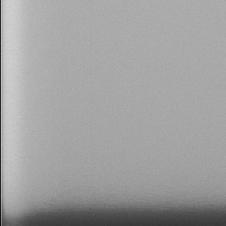
6) Display "Zero.fits" to be sure it looks reasonable. Our zeros are usually pretty uniform everywhere. The first column (X=1) is often significantly higher, and the next few columns (2<X<5) are often a tad higher, but this is normal. The median value of Zero.fits should be around at about 505 +/- 5 counts, and a typical zero image looks like this. Discuss your Zero.fits with Andy if there are any questions.
* If you don't have one already, open an ximtool (image display) window by typing in your IRAF window:cc> !ximtool & cc> set stdimage=imt1024 cc> display Zero.fits 1 cc> imstatistics Zero.fits fields="image,midpt"
Updated 2002 May 29 -- ACL
Overview: Every time we take an image, whether there is light falling on the chip or not, a small number of counts appears in each pixel due to "dark current" in the chip (thermal motion of the atoms knocks loose some electrons). The amount of dark current is proportional to the exposure time (i.e., it appears at a constant rate, counts/sec). The amount of dark current varies from pixel to pixel, and tends to be larger when the chip is operated at a higher temperature (faster atomic motions in the silicon chip knock off electrons more frequently).
To correct for the dark current, we have created a number of "dark frames" -- high signal-to-noise images recording the counts in each pixel -- each at a different temperature. In this step, we create a dark frame with the temperature matching the temperature setpoint in our observations by using "linear interpolation" beteween the actual dark images immediately cooler and warmer than our CCD temp. Later, when we run CCDPROC on the star and skyflat images, IRAF will scale this dark frame (darktime=500sec) to the darktime of each image and subtract off the scaled dark image.
1) First, determine the average CCD temperature for your star images from the temperature recorded in several image headers. The first command creates a file called 'ccdtemp' that contains the CCD temperature from the header of each of your star images. Page the file to see what it looks like. The last command uses the CURFIT task to fit a flat line (order=1) to these data, when you hit 'q' to quit, it will print a mess of stuff to your screen, the last line of which is the mean (average) temperature for the night (note that it is in exponential notation!!). Write that number on scrap paper as TCCD:
cc> hselect *_*.fits UT,CCD-TEMP yes > ccdtemp
cc> !page ccdtemp
cc> curfit ccdtemp function=legendre order=1 power+
2) Next, see which temperatures have dark frames available:
cc> imhead /data/layden/BGTEL/DARKS/DarkT*.fits
3) The dark current increases quickly at hotter temperatures, so we must interpolate between the the dark frames with temperatures immediately above and below our CCD operating temperature. Select from the list in Step 2 the temperatures immediately above and below TCCD: call them T2 (above) and T1 (below) -- write them on your scrap paper. The fractional contribution of each dark frame to our final dark is then (here is how these equations are derived from linear interpolation):
4) The next step will copy fractions of each dark image to the current directory, and then add them together to get the final dark that is appropriate to our TCCD. Let's say the dark frame with T1is called 'DarkTmNN.fits', and the one with T2 is called 'DarkTmMM.fits'. To help you remember which files you used, write the values for NN and MM on your scrap paper following this example:
| T2 = +0.13 | MM=T00 | Cts2 = 317.0 |
| TCCD = -1.02 | LDark.fits | CtsCCD = |
| T1 = -2.72 | NN=Tm03 | Cts1 = 225.7 |
Note: for f1 and f2, you should substitute the numbers you computed in Step 3, and for NN and MM, you should substitute the names of the dark frames with temps below and above TCCD, respectively.
cc> epar imarith [set pixt=r, calct=r, hparams=darktime]
cc> imarith /data/layden/BGTEL/DARKS/DarkTmNN.fits * f2 D1.fits verb+
cc> imarith /data/layden/BGTEL/DARKS/DarkTmMM.fits * f1 D2.fits verb+
cc> imarith D1.fits + D2.fits LDark.fits verb+
cc> unlearn imarith
5) Let's check to see that all worked properly by checking the median counts in your interpolated dark image:
cc> imstat *D*.fits[100:924,100:924] fields="image,midpt" upper=17000
Write the midpt values for LDark in the box labeled CtsCCD in your table -- it should be between Cts2 and Cts1. Let's check graphically whether this is the correct "linear interpolation" between the dark images immediately warmer and cooler than the CCD temperature you observed at. To do this, edit the file containing the darkcounts vs. temp data for the darks (dark_temp.dat) and add a line at the bottom with the CCD temp and dark count rate (midpt) from LDark (put a "90" in the third column to plot these points with an open circle). Then plot the graph using SuperMongo (SM):
cc> emacs dark_temp.dat &
cc> !sm
: macro read sm.dark_temp
:plt
:quit
You should get a plot in the SM window. The solid symbols and the line connecting them are the sequence of dark images taken at different temperatures, and the open circle is your "interpolated" dark image. It SHOULD lie exactly on the line connecting the solid symbols. If you aren't sure, you can zoom in by editing the sm.dark_temp file and changing the X and Y limits below the line marked CHANGE TO ZOOM, then replot using SM. If the open circle does not fall on the line, something is amiss -- see Andy!
Also, the darktime for LDark should be 500 sec:
cc> hsel *D*.fits $I,darktime yes
Finally, display the dark image -- it should look very grainy, something like this:
cc> displa LDark.fits 1
cc> implot LDark.fits
Obtaining the correct dark image is a tricky procedure. If you have any doubts, ask Andy. Here is an example that may clarify the procedure.
Updated 2010 Nov 18 -- ACL
Overview: The purpose of the flat field images is to remove the variations in sensitivity from one pixel to the next across the CCD chip. In general, there are small-scale features (1-100 pix across) caused by variations in the light sensitivity of the CCD semiconductor material, electronics, and "dust rings" -- concentric circular features that are out-of-focus shadows of dust particles on the CCD window and/or filter. There also tend to be larger scale features (>100 pix) caused by partial shadowing ("vignetting") within the light path of the telescope and camera. If we observe a uniformly bright source (a "flat" source) like the clear night sky, the pixels with lower sensitivities (for whatever reason) will record lower numbers of counts, and we get a 2-D map of the CCD's sensitivity. In this section, we will create this map. In the next section we will correct for the sensitivity variations by DIVIDING each object (star/cluster) frame by the map, thus increasing the measured counts in the pixels we know to be under-sensitive to have the intensity level they should have had if the telescope/CCD were perfect. The pixel sensitivities may depend on the color of the light they are seeing, so we must take flats through each filter we will use that night.
In principle, the clear twighlight sky is a pretty uniform light source. If we got ~4 "skyflats" in each filter (VRI) during dusk twilghlight, and ~4 more during dawn twilight (to even out any East/West variation due to the direction of the sun), we could create a really nice combined skyflat in each filter. Occasionally we can do this, but real life is messy, and it is not always perfectly clear and moonless (another potential light source) both dusk and dawn. Nor do we always stay up observing all night. So, we are using a "hybrid" method to try to get good flat field images on our sub-perfect nights.
During your observing, you probably took "dome flats" of the lamp-lit dome wall. Here, after we correct the images for non-linearity, we will TZD-process them to remove the "additive" problems. Then, we combine the dome flats into a single, high-signal image with cosmic rays removed for each filter.
In Step 6, if you took any twilight sky flats or dark-sky flats, we will TZD-process them and save them for future use. If you got lots, we may use them here, ask Andy (if so, we will follow the method here for Flats and Objects).
Last, we will download some archived skyflats that Andy has selected and combined, ccdproc them using your new domeflat (a division; this puts the 2-D "signature" of the dome flat into your skyflat), and then smooth it heavily to remove all the small-scale structure. What's left is a 2-D map of the large-scale variation between the ideal sky and the non-uniformly illuminated dome. We will use this along with the combined dome flats in the next step to fully flatten the object (star/cluster) images. To better understandand visualize the information flow through this rather complicated process, visit this link.
1) In the current program, you will have obtained domeflats the V and I filters, and perhaps also in R. In this example, we will assume the V filter is being used. Make a list of all the domeflats using the FILES command, and edit it with emacs as needed. Copy this list into separate lists for each filter, and edit each to retain only the images taken in that filter:
cc> files *dflat*.fits >> dflat.list
cc> emacs dflat.list (remove any incorrect file names; list of all VRI domeflats)
cc> cp dflat.list dflatI.list
cc> emacs dflatI.list (remove any file names for V and R; repeat for dflatV.list and dflatR.list)
2) Process the dome flats. Here we will trim them, zero-correct, and dark-correct them using the task CCDPROC; since none of these corrections is color-dependent, we can do them all in one go (dflat.list). Ensure all went well using CCDLIST (the processed files should have [TZD]).
cc> cl < dpar.ccdproc_flat
cc> lpar ccdproc
cc> ccdproc @dflat.list zero=Zero.fits
cc> ccdlist @dflat.list
3) The CCD has begun to behave non-linearly. That is, doubling the amount of light does not result in twice the counts for a fixed brightness object. About once a year, we collect a set of dome flats of varying exposure level and use these data to determine a polynomial correction function (see Andy for details). This correction is not color-dependent, so we can correct all the dome flats in one go as follows (the coefficients in green will change from year to year -- updated 2010feb16 -- if you are working on data taken before this date, see Andy!):
cc> imreplace @dflat.list val=99999 low=11500 upp=INDEF
cc> imreplace @dflat.list val=-500 low=INDEF upp=-500
cc> irred
ir> irlincor @dflat.list @dflat.list coeff1=1.0875 coeff2=-0.9173 coeff3=2.4086
ir> bye
cc> imarith @dflat.list + -38.9171 @dflat.list  calctype=real hparam=''
cc> hedit @dflat.list f_lincor "yes_2010feb" add+ ver-
4) Combine the dome flats for a given filter into a single, high signal-to-noise final flat, "DflatI.fits" (or "DflatV.fits" if you are working with the V filter, or "DflatR.fits"). It will use the "minmax" rejection algorythm to remove cosmic rays. It looks at all the intensity values at a given pixel (say, X=124, Y=456), throws out the nlow lowest intensity values and the nhigh highest values, and averages the remaining values, according to the table below. For example, if we took 9 domeflats in I, we would have Nflats = 9 pixel values; it would throw out the lowest value and the two highest values, then take the average of the remaining 6 values. [If you want to learn more about the ways we can reject discrepant pixels, type "help flatcombine" and focus on the rejection algorithms, or visit this webpage.]
| Nflats | nlow | nhigh |
|---|---|---|
<7 |
0 |
1 |
7 to 12 |
1 |
2 |
>12 |
1 |
3 |
cc> cl < dpar.flatcomb
cc> epar flatcombine  [change nlow and nhigh to match the values in the table for your Nflats]
cc> flatcombine @dflatI.list out=DflatI.fits  [or DflatV.fits, or DflatR.fits -- one file for each filter]
cc> ccdlist DflatI.fits
5) Display your final dome flats to be sure they look reasonable. There should be no cosmic rays, and the intensities should drop as you move from the center toward the corners. There may be some "bad pixels" scattered here and there that just won't flatten out. They should look something like this. Discuss the flats with Andy if there are any questions.
cc> display DflatI.fits 1 [or DflatV.fits, or DflatR.fits -- one file for each filter]
6) Process any skyflats you took. Here we trim them, zero-correct, and dark-correct them using the task CCDPROC. Ensure all went well using CCDLIST (the processed files should have [TZD]), then we do the linearity correction (coefficients updated 2010feb16) . If you didn't take any skyflats, skip this step; if you do have skyflats, email Andy to remind him to archive them.
cc> cl < dpar.ccdproc_flat
cc> lpar ccdproc
cc> ccdproc *sflat*.fits zero=Zero.fits dark=LDark.fits
cc> ccdlist *sflat*.fits
cc> imreplace @sflat.list val=99999 low=11500 upp=INDEF
cc> imreplace @sflat.list val=-500 low=INDEF upp=-500
cc> irred
ir> irlincor @sflat.list @sflat.list coeff1=1.0875 coeff2=-0.9173 coeff3=2.4086
ir> bye
cc> imarith @sflat.list + -38.9171 @sflat.list  calctype=real hparam=''
cc> hedit @sflat.list f_lincor "yes_2010feb" add+ ver-
7) Now we will download some archived skyflats that Andy has built for this observing season. Andy selected the best skyflats: those with no clouds or moon. Also, he tried to take four dusk skyflats (where the setting sun is in the West) and four dawn skyflats (where the rising sun is in the East) to balance out any slight non-uniformities in the sky brightness. He also tried to select nights when TCCD was low, to minimize noise from the dark signal and imperfectly corrected warm/hot pixels. He combined them using flatcombine/minmax to reject cosmic rays and stars, producing SkyF.fits, where F = VRI represents the filters we used. You should select the flats that best suit the time of your observing night, and copy those images into your current directory:
cc> ls /data/layden/BGTEL/SFLATS/*.fits
cc> cp /data/layden/BGTEL/SFLATS/SkyV2010.fits SkyV.fits
   [master skyflats for the 2010 observing season, use the year you observed; do R & I too]
8) Now we will use CCDPROC to divide the SkyF flats by the DflatF domeflat of the corresponding filter F. This puts the 2-D "signature" of the dome flat -- most importantly the large-scale structure due to the poor, non-uniform illumination of our dome wall -- into the resulting skyflat. It also divides away (at least to first order), much of the small-scale structure like dust rings.
cc> lpar ccdproc
cc> ccdproc SkyI.fits flatcor+ flat=DflatI.fits
cc> ccdproc SkyV.fits flatcor+ flat=DflatV.fits
cc> ccdproc SkyR.fits flatcor+ flat=DflatR.fits   [if you took R-filter images this night]
9) Now we will smooth (heavily!) these flats to remove any remaining small-scale structure (pixel to pixel variations in sensitivitiy, dust rings, etc). What's left is a 2-D map of the large-scale variation between the ideal (flat) sky and the non-uniformly illuminated dome. The resulting images are called illumination corrections. Display them; they should look vary much like the SkyF images from the previous step, except very smooth with all the bad pixels removed. We will use them along with the combined dome flats in the next sequence of steps to fully flatten the object (star/cluster) images.
cc> mkskycor SkyI SkyIsm xboxmin=5. xboxmax=0.1 yboxmin=5. yboxmax=0.1 clip+
cc> mkskycor SkyV SkyVsm xboxmin=5. xboxmax=0.1 yboxmin=5. yboxmax=0.1 clip+
cc> mkskycor SkyR SkyRsm xboxmin=5. xboxmax=0.1 yboxmin=5. yboxmax=0.1 clip+
cc> display SkyIsm.fits 1   [and for other filters you used; they should be smooth but retain large-scale structure]
Updated 2010 Oct 11-- ACL
Overview: First, we will run CCDPROC on all the star (object) images to do the "additive" corrections: (a) trim them, (b) subtract "Zero.fits" to remove the bias level (about 500 counts) and the 2-D structure produced when the chip is read out, (c) subtract off the appropriate-temperature dark image. Then, we correct these images for the CCD's non-linearity. Finally, we will do the "multiplicative" corrections: (d) divide by the appropriate dome flat field image (e.g., "DflatI.fits"; this should remove small-scale structures like pixel sensivity and dust rings), and (e) multiply by the illumination correction image to remove the large-scale non-uniform illumination pattern in the dome flats. The resulting images will be completely processed and ready for photometry.
1) Using FILES, create a list of all the star/cluster images you took (they should all be through either the V, I or R filter), and they should all have an underscore ("_") in them. Use CCDRED to check to be sure no spurious images (biases, flats, Zero, Flat*, Dark*) have crept in. If they have, remove their names from the list using EMACS. Then, create separate lists containing only the V, I, and R images:
cc> files *_*.fits >> star.list
cc> ccdlist @star.list
cc> emacs star.list   [if needed; this lists star images in all filters, V, R, & I]
cc> files *_*i?.fits >> starI.list
cc> emacs starI.list  [as needed]
cc> files *_*v?.fits >> starV.list
cc> emacs starV.list  [as needed]
cc> files *_*r?.fits >> starR.list
cc> emacs starR.list  [as needed]
2) Set the parameters for CCDPROC and run CCDPROC to do the Trim, Zero, and Dark corrections to each star image. These are not color-dependent, so do all the images at once (star.list). Use CCDLIST to ensure that the processing has gone well ([TZD] for all star images).
cc> cl < dpar.ccdproc_star
cc> lpar ccdproc
cc> ccdproc @star.list flatcor-
3) The CCD has begun to behave non-linearly. That is, doubling the amount of light does not result in twice the counts for a fixed brightness object. We can correct for this as follows (the coefficients in green will change from year to year-- updated 2010feb15 -- if you are working on data taken before this date, see Andy!):
cc> imreplace @star.list val=99999 low=11500 upp=INDEF
cc> imreplace @star.list val=-500 low=INDEF upp=-500
cc> irred
ir> irlincor @star.list @star.list coeff1=1.0875 coeff2=-0.9173 coeff3=2.4086
ir> bye
cc> imarith @star.list + -38.9171 @star.list  calctype=real hparam=''
cc> hedit @star.list f_lincor "yes_2010feb" add+ ver-
4) Set the parameters for CCDPROC and run CCDPROC to apply the dome flat field to each star image (use "flat = DflatV.fits" if you observed with the V filter). Use CCDLIST to ensure that the processing has gone well ([TZDFI] for all star images; the FI got done in this step). This should remove the small-scale artifacts like pixel-to-pixel sensitivity and dust rings from the images.
cc> lpar ccdproc
cc> ccdproc @starI.list flatcor+ flat=DflatI.fits illumcor+ illum=SkyIsm.fits
cc> ccdproc @starV.list flatcor+ flat=DflatV.fits illumcor+ illum=SkyVsm.fits
cc> ccdproc @starR.list flatcor+ flat=DflatR.fits illumcor+ illum=SkyRsm.fits   [if needed]
cc> ccdlist @star.list
4) Display several of the images in different filters to be sure the processing looks reasonable. The sky should appear pretty uniformly gray (i.e., constant brightness). On some images, there are long, curving features -- we think these are caused by reflections inside the telescope, the light of bright stars glinting off a corner or shiny surface along the light path. For now, we gotta live with them. Discuss the images with Andy if there are any questions.
cc> display N5904_1i2 1 [etc]
5) Create a file called "processing.doc" in which you record any anomalies or concerns that you have about the processing procedure (eg, you might mention if only 5 flats got used... 8 or 10 would have been better) or with the images you have inspected (eg, changes in brightness of the sky with position on the chip, or nasty "ghost images"). This is a good place to record any comments that were written on the paper log sheet by the observer (eg, "Clear sky at dusk, great flats!", "Full moon rise at UT=2:15", or "Patchy clouds move in around UT=4:30, thicken till force close at UT=5:40").
cc> emacs processing.doc &
Updated 2011 May 24 -- ACL
Once you are satisfied with your processing, email Andy <laydena(at)bgsu(dot)edu> with the directory path of your final images, and a list of the clusters you observed. I will inspect the images, and if all looks good, I will notify the people who are responsible for doing the photometry on the various stars. These people will copy the images into their own accounts for the photometry.
Andy will make DVD copies of the raw and processed images for the archive. If we need to reprocess or re-photometer the data at some time in the future, we can recover the images from the DVDs.
Andy will tell you when and how to delete the images from your account.
Updated 2010 Feb 18 -- ACL