VOLTAGE−CURRENT CHARACTERISTICS
PROCEDURE
2. Open the back of the component box supplied and compare the circuit to Fig. 2.06-3a. Note that the black terminal is common to each circuit element. For this experiment, when the positive side of the voltage source is connected to a colored terminal the resulting voltage drop across and the current through the circuit element will both be considered to be positive. Negative voltages and currents result when the black terminal is connected to the positive side of the voltage source and a colored terminal is connected to the negative, or grounded side.
3. Assemble the circuit shown in Fig. 2.06-3b, taking special care to be certain the ammeter is connected properly (i.e. all current from the source must go through the ammeter). For all parts of this experiment be certain that the current does not exceed 0.2A. Currents stronger than this can damage the power supply.
4. Red-Black Terminals
Measure V vs. I for V from 0 to 30V in steps of about 3V. See procedure 1 and repeat for 0 to −30V. Record the data in the table at cells B13:F22.
5. Blue-Black Terminals
Repeat procedure 4 for the
blue terminal circuit element. Record the data in the table at cells B28:F37.
Figure 2.06-3: Test Circuit for V-I Characteristic Measurements
For the Yellow terminal circuit
element an added resistor is needed in the circuit to help limit the total
current. Add a 150 Ω,
25 W resistor as shown in Fig. 2.06-4a. Record the data from the
procedure below in the table at cells B44:F55.
b. Reverse the circuit element
(negative voltage on yellow) remove the 150 Ω
resistor, and measure I vs. V for voltages from 0 to 30 volts in 3 volt steps.
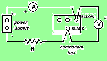
Figure 2.06-4: Test Circuit for Step 6