| Double Slit/Grating Equation | maxima | |
||||
| Double Slits | minima | |
(n = 0, ±1, ±2, ...) |
PRELAB
PURPOSE
To study the dispersive properties of the diffraction grating and its use in measuring the wavelength of light.
EQUIPMENT Pasco optical bench, light source, viewing screen, diffraction plate, diffraction scale, slit mask, sodium lamp.
RELEVANT EQUATIONS
| Double Slit/Grating Equation | maxima | |
||||
| Double Slits | minima | |
(n = 0, ±1, ±2, ...) |
DISCUSSION
The diffraction grating is a set of many closely spaced slits which allow light to pass through them and the interference pattern from all the slits produces areas of color when the grating is illuminated with white light. The geometry of two of these slits is shown below in Fig. 14-1.
At an arbitrary point on the projection screen P, the light from each slit will have traveled a different distance to get to P. In general then, there will be a difference in phase between the two waves. For example, if the path difference Δx traveled by the two waves is an integral number of whole wavelengths, then they arrive at point P in phase and will constructively interfere with each other, producing a bright fringe on the screen.
Figure 14-1: Geometry of Double Slit Interference
We can express this relation as a condition for a maximum in the
intensity pattern on the screen:
| maxima: Δx = nλ (n = 0, ±1, ±2, ...) | (1) |
This is equivalent to a path difference of an even number of half-wavelengths. On the other hand, if the two waves arrive at the screen with a path difference of precisely an odd number of half-wavelengths; then they are 180° out of phase and they will destructively interfere, producing zero intensity (a dark fringe) at the point on the screen. This relation is expressed as:
|
minima:
|
(2) |
The path difference between the two waves can be expressed in terms of the geometry of the set up. Let the distance from the slits to the projection screen be D and the location of point P on the screen be s units from the centerline.
Point P can be designated either by specifying s and D or by specifying the projection angle θ from the centerline. These quantities can be related using trigonometry (see Fig. 14-1):

or
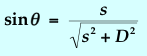 |
(3) |
In Fig. 14-2, look at the small right triangle constructed just
beyond the slits. It is evident that the path difference between the
two waves is simply equal to the smaller leg of the triangle. We can write:
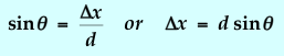 |
(4) |
Figure 14-2: Close-up View of the Double Slit Geometry
The conditions for maxima and minima with two slits are
maxima:
![]()
|
minima:
|
(5) |
where (n = 0, ±1, ±2, ...).
Diffraction Grating
The diffraction grating is a collection of multiple slits. It is an amazing fact that the interference from such an array produces maxima that are located at the same positions as given by eqn. (5) above. However, whereas in the double-slit situation, the maxima are just as wide as the minima, in the case of the grating, the maxima are quite narrow. In fact, the improvement in the sharpness of the maxima is proportional to the total number of slits in the grating. The sharp division between the interference maxima for different wavelengths is useful for separating different wavelengths from a complex light source. The grating is therefore widely used as a dispersive element in optical systems.
Print out and complete the
Prelab questions.