Figure 8-1: An R-C Circuit with a DC Source
PRELAB
PURPOSE
You will study the response of an RC circuit to square wave voltages, determining the time constant of the circuit and comparing it to the theoretical value.
EQUIPMENT oscilloscope, R-C breadboard, function generator, 2 BNC to twin-banana cables, BNC to single-banana cable.
DISCUSSION
An RC circuit consists of a capacitor connected in series with a resistor and a dc power source as shown in Fig. 8-1.
Figure 8-1: An R-C Circuit with a DC Source
When the switch is closed, an initially uncharged capacitor
will gradually build up charge, with the voltage approaching
its full value of Vo as time
passes, as shown in Fig. 8-3. The voltage across the capacitor
will reach 63% of its maximum value in a time interval determined by the
resistance (in ohms) and the capacitance (in farads) of the circuit.
The exact formula for the charging curve is
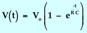
where the quantity "e" is a constant, equal to 2.718..., the base for natural logarithms.
Consider the circuit in Fig. 8-2.
Figure 8-2: Discharge Circuit of a Capacitor through a Resistor
When the switch is closed, the capacitor that is initially
charged to a voltage level of Vo
will discharge through the resistor R according to the relation
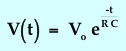
and since e-1 = 0.37, after RC seconds, the capacitor voltage will be 37% of the starting value. The discharge curve is also illustrated in Fig. 8-3.
Figure 8-3: Charge and Discharge Curves of Capacitor Voltage
vs. Time for an R-C Circuit
Print out and complete the
Prelab questions.