| Time Constants | τ = L / R | for the LR circuit | |
| τ = RC | for the RC circuit | ||
| Free Oscillations | |
||
| Inductive Reactance | XL = 2π f L | ||
| Capacitive Reactance | XC = 1 / (2π f C) | ||
| Total Impedance | |
||
| Ohms' Law | Im = Vm / Z |
PRELAB
PURPOSE
To observe oscillations and resonance in an RLC circuit.
EQUIPMENT function generator, oscilloscope, RLC breadboard, ohmmeter, 2 BNC-to-twin-banana cables, BNC-to-single-banana cable.
RELEVANT EQUATIONS
| Time Constants | τ = L / R | for the LR circuit | |
| τ = RC | for the RC circuit | ||
| Free Oscillations | |
||
| Inductive Reactance | XL = 2π f L | ||
| Capacitive Reactance | XC = 1 / (2π f C) | ||
| Total Impedance | |
||
| Ohms' Law | Im = Vm / Z |
DISCUSSION
I. Determination of L and C
For either an LR or RC circuit in which a current is flowing initially, the current will decay to zero exponentially when all external sources of emf are removed. Since the voltage across the resistor is directly proportional to the current through the resistor, the voltage across R at time t will be given by
where Vo is the initial voltage at t = 0 and τ is the time constant of the circuit:
τ = L / R for the LR circuit
τ = RC for the RC circuit.
The value e-1 = 0.37, so when the voltage V reaches 0.37 Vo, a time equal to one time constant has elapsed. We will directly measure the time required for the voltage across the resistor to decay to 0.37 times its initial value. We will also directly measure the resistance value. These two results will allow us to calculate (determine) the inductance of the coil and the capacitance of the capacitor.
II. Free Oscillations in an LCR circuit
Consider a charged capacitor that is connected across a pure inductor (no resistance) as illustrated in Fig. 9-1. Let the capacitor initially be fully charged and the initial current be zero. When the switch is closed, the capacitor begins to discharge as charge flows through the inductor, and the current rises. The electrical energy that was initially stored in the capacitor will be transferred to magnetic energy in the inductor.
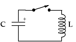
Figure 9-1: An L-C Circuit
When the capacitor has fully discharged,
the current through the inductor reaches a maximum and begins to decrease.
The collapsing magnetic field will induce a voltage in the coil in the
direction that opposes the change in magnetic flux. This tends to maintain
the current and will recharge the capacitor with the polarity opposite
to what it had originally.
With the capacitor fully charged (but with opposite polarity), the current reaches zero again, and the process repeats itself. This continual oscillation of charging and recharging would go on forever if there were no dissipative effects. The frequency at which these oscillations occur is the natural frequency of the circuit and is equal to
.
The resistance present in the circuit dissipates the electrical energy (transforms electrical energy into heat) and the oscillations decrease in amplitude as time goes on. If the resistance is not too large, the damped oscillations occur at a frequency that is close to the natural frequency.
In this experiment, a square wave voltage applied to the circuit is used to initially charge the capacitor and the damped oscillations which result will be observed.
III. Forced Oscillations and Resonance
An inductor, capacitor and resistor connected in series will offer opposition to sinusoidal alternating current flow that is determined by the total circuit impedance. The sinusoidal current that flows due to an external sinusoidal voltage (sine wave generator) has an amplitude that is determined by the values of L, C, and R, and by the frequency of the applied voltage.
These oscillations are 'forced' since they result from an external sinusoidal voltage. The total circuit impedance is given by
where XL = 2 π f L and XC = 1 / (2 π f C).
The current, i(t), is directly proportional to the voltage across the resistor:
i (t) = VR (t) / R.
The root-mean-square (rms) value of current is determined by the rms value of the applied voltage and by the impedance:
Vapp = Irms Z
where Vapp and Irms are the rms values of applied voltage and circuit current respectively. Since sinusoidal peak values are related to rms values by the following relations:
Vm =
Vapp
Im =
Irms
We can write Vm = Im Z or Im = Vm / Z.
If the amplitude of the applied voltage remains constant
while the frequency of the applied voltage is
changed, the current will change and will be a maximum when Z is
a minimum; i.e. close to the natural oscillation frequency of the circuit,
.
This phenomenon is called resonance and the frequency dependence of the
current in the circuit is illustrated in Fig. 9-2.
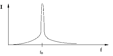
Figure 9-2: Resonance in the Current of an RLC Circuit
Print out and complete the
Prelab questions.