ELECTRICAL MEASUREMENTS WITH DIRECT CURRENT
PRELAB
PURPOSE
To learn about Kirchhoff's laws and how to apply them to several different electrical circuits. To understand the details of series and parallel connections.
EQUIPMENT two 6 -volt lantern cells, two 6-volt lantern bulbs, voltmeter, ammeter, rheostat, knife switch.
RELEVANT EQUATIONS
Kirchhoff Voltage Law: ![]()
Kirchhoff Current Law: ![]()
DISCUSSION
The motion of electric charges around a closed circuit (electrical current) is in many ways similar to the flow of liquid through a closed hydraulic system such as the circulatory system of the human body, driven by a pump such as the heart. The fluid flows into the intake of the pump at low pressure and through internal mechanical action is expelled from the outlet at a higher pressure. The fluid is thus forced through an external circuit of pipes and other devices where it loses potential energy and flows back to the inlet of the pump.
ELECTROMOTIVE FORCE & POTENTIAL DIFFERENCE
The analogous component to the pump in electrical circuits is called a seat of electromotive force(emf) and can take the form of a device such as a battery, generator, or solar cell. In the same way that a water pump transfers mechanical energy into the energy of the fluid (its ability to do work as it flows), a seat of emf transfers one form of energy into the potential energy of electric charges; for example, in the case of the battery, stored chemical energy is converted into electric energy. It is convenient to speak of the electrical potential energy per unit charge at a given point in an electric circuit. This quantity is defined to be the electric potentialat that point, and the unit of measure for this quantity is the volt .
When describing the properties of a seat of emf, the differencein the potential at the outlet or positive terminal (+) and the inlet or negative terminal (-) is usually the measurable quantity. This is analogous to the pressure difference between the intake and outlet of a fluid pump and indicates the charge "pumping" ability of the device: usually simply referred to as the voltage or emf. When a seat of emf is connected to a closed circuit, positive charge is pumped out of the positive terminal and flows around the circuit back to the negative terminal of the seat of emf. As it flows, the charge gives up its electrical potential energy into other forms of energy such as heat and light when flowing through a light bulb, or rotational motion when flowing through a motor. The moving charge ends up with less electrical potential energy when it leaves these devices than when it entered. The potential is thus less on leaving than it was upon entering, and the difference in potential(voltage) between the exit point and the entry point is negative.
An electric circuit provides a clear demonstration of the principle that energy in all its forms is always conserved, since the rate at which electrical energy is supplied by a seat of emf is equal to the rate at which it is converted to other energy forms in the circuit. The statement of this conservation principle for an electric circuit is called Kirchhoff's voltage law, referred to here as KVL.
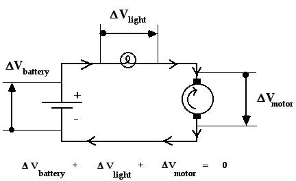
Figure 16-1: Kirchhoff's Voltage Law in a Simple Circuit
This law states; at any instant of time, the sum of all the potential differences (voltages) around a closed circuit is equal to zero. A demonstration of KVL is illustrated in Fig. 16-1, where the sum of the voltages is:
![]()
Note that in applying KVL all
potential differences are measured in the same sense relative to the direction
of current flow. In Fig. 16-1, the voltage measured across
the battery will be positive while the voltage measured across both the
light bulb and the motor will be negative when measured in the same direction
of current flow as indicated.
The instrument used to measure the potential difference between two points is called a voltmeter. It is always connected across two points using leads distinguished by polarity (plus and minus) because it measures only the voltage between the two points rather than obtaining a value for the potential at each point separately.
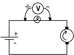
Figure 16-2: Connecting a Voltmeter to Measure DV across the Light Bulb
The reading on the voltmeter will indicate the potential at the positive (+) terminal minus the potential at the negative (?) terminal. The proper connection of a voltmeter to a circuit is shown in Fig. 16-2. Ideally the voltmeter itself should not provide an easy path for charge to flow through it between the two measurement points, because then the measured value would be affected. In practice, this ideal is approximated quite closely by the digital voltmeter.
CURRENT
The rate of flow of electric charge in a circuit is defined as the current,measured in Coulombs of charge per second, a unit also known as the ampere. In the single loop circuit example treated earlier, the electric current is the same at every point around the circuit. However, if the circuit is more complex (that is, made up of two or more loops) the current can in general be different in each loop. The various currents can be related to each other by considering another fundamental principle: conservation of charge.
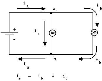
Figure 15-3: Kirchhoff's Current Law in a Double Loop Circuit
This law states that charge cannot spontaneously appear or disappear at any point, and so at any junction between two or more branches of a complex circuit the rate at which charge enters the junction must be equal to the rate at which it leaves the junction. This observation leads to a statement of Kirchhoff's current law, or KCL: At any instant of time, the sum of the currents flowing into any point in an electric circuit is equal to the sum of the currents flowing out of it. This principle is demonstrated for a junction in a multi-loop circuit in Fig. 16-3, where we can write:
![]()
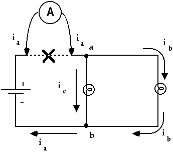
Figure 16-4: Connecting an Ammeter to Measure the Current through the Battery
The instrument used to measure electric current is called the ammeter(a contraction of ampere-meter). Since it is necessary for the current to actually flow through the ammeter, it is always connected by breaking into the leg of the circuit where the current is to be measured and inserting the instrument to bridge the gap.
The terminals of an ammeter are
distinguished by polarity (plus and minus) markings, and current is indicated
as being positive when it flows into the positiveterminal and out
of the negativeterminal. An example of an ammeter connected to a circuit
is illustrated in Fig. 16-4.