Hey all,
Here's a first installment on boatbuiling report. Started laying out the hull parts on 1220 x 1500mm plywood sheets Friday. I don't have what anybody would call complete plans for the boat, just a rather sparse 3d computer model which allowed me to do the necessary weight & balance calculations and to create flat panel expansions for the main hull panels (if Shawn likes to follow along, he may be reminded of the cardboard Motor Lifeboat model we made together last time Karen & I were visiting. In that case the panels were already printed on the card stock; we had to cut them out and glue & tape them carefully together.
Below, I am marking out the panel shapes using 2 rulers.
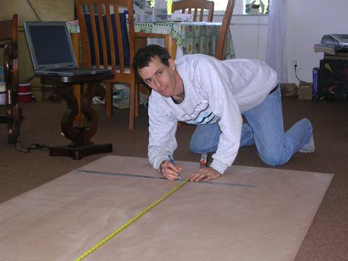
The 3d file exists only in the computer (can be printed out but there's no reason to), I just brought the laptop to the work in the living room, queried distances straight from the screen and layed them off on the plywood with no scaling to worry about as when working from scale paper drawings. On the computer image below, the outer white rectangle represents the plywood sheet, the curved white lines are the hull panels (sides in this case, others are not shown here, the red vertical lines form a grid to pick up meassurement points from. Has Shawn been exposed to graphing points on the Cartesian plane at school? This is a demonstration of exactly the same thing.
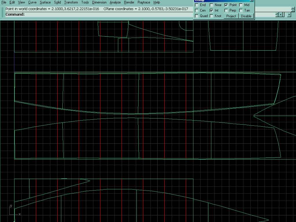
After graphing a set of points along the curves, I use a flexible wood batten (spline) to connect the dots into a smooth curve (see picture below). Running a pencil along the spline marks the panel outline; later I'll cut the panels out with a hand saw & tape them together with fiberglass tape and epoxy, pretty much the same as the cardboard model.

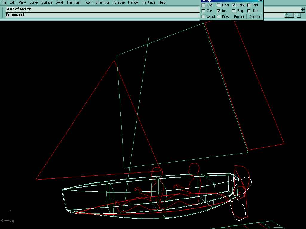
Also attached is a screen shot of the whole 3d model to give a small dea of how this thing looks.
That's all I ave for now, more to follow when it happens.
Karen says I should put in www. indianriverlagoon.org, says it is a fun link.
Matt